GOAL: Protect people and property by spotting wildfires sooner.
Using AI-powered pattern recognition, light-weight carbon fiber, autonomous navigation, advanced controls and solar power, the Stork will soon go into service.
Systems
-
![]()
Imaging
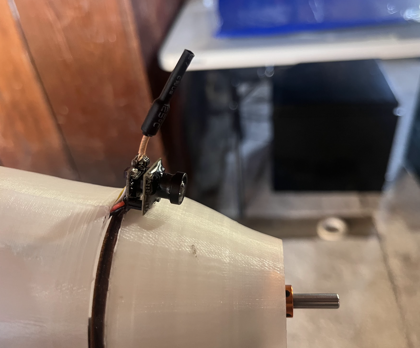
Two cameras (one telephoto and one wide angle) provide image resolution of 25 centimeters per pixel at 2,000 feet.
-
![]()
AI Recognition
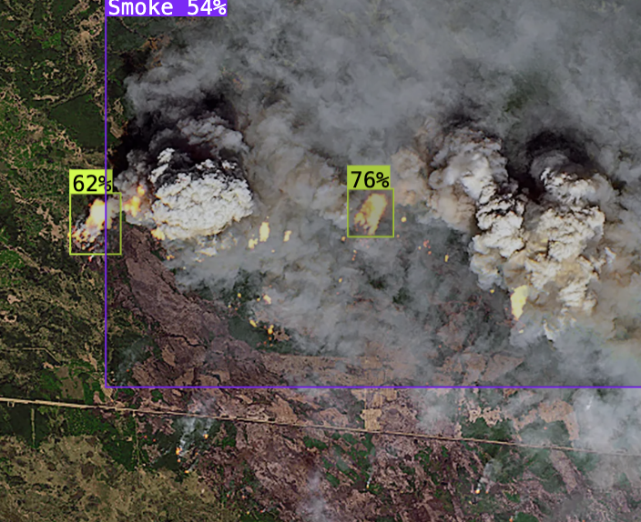
YOLOV8 CNN image identification system identifies possible fires and distinguishes them from natural phenomena.
-
![]()
Sensors
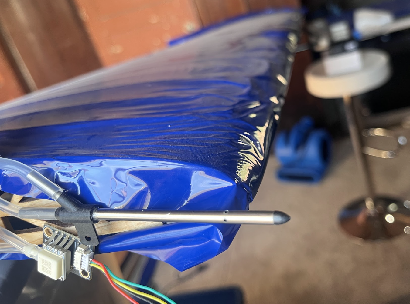
Seventeen different sensors provide real time information on the aircraft’s characteristics from airspeed to internal temperature.
-
![]()
Navigation
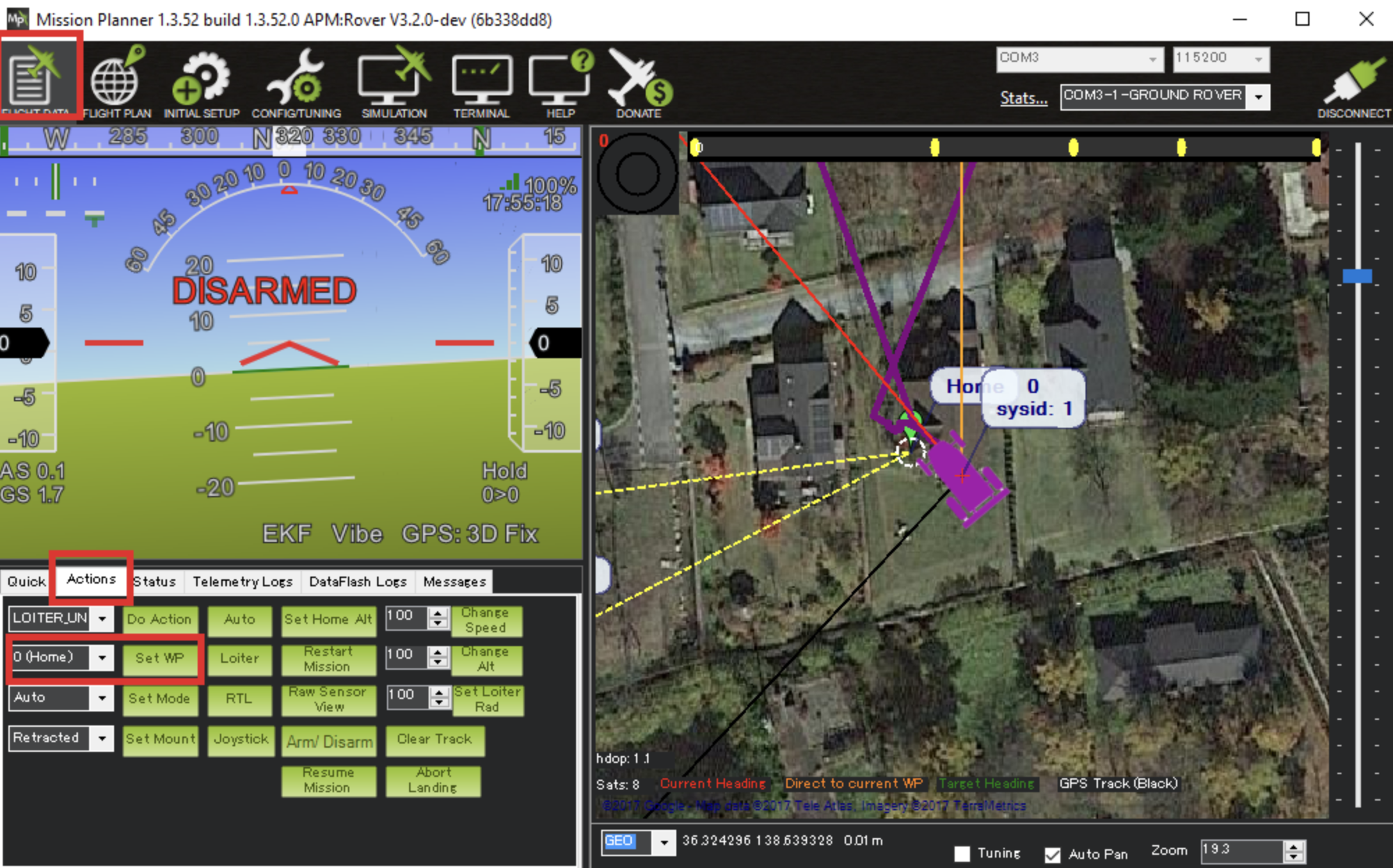
Ardupilot auto-pilot system allows for fully autonomous flight with increased efficiency thanks to thermal detection and optimization.
-
![]()
Communication
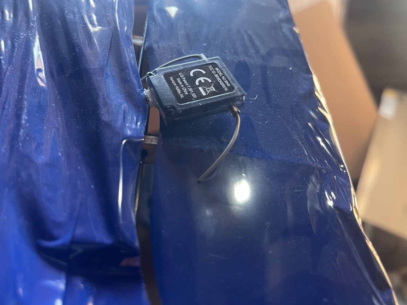
Dual radio and cellular connections provide increased reliability while extending the maximum range to anywhere with cell service!
-
![]()
Solar Panels
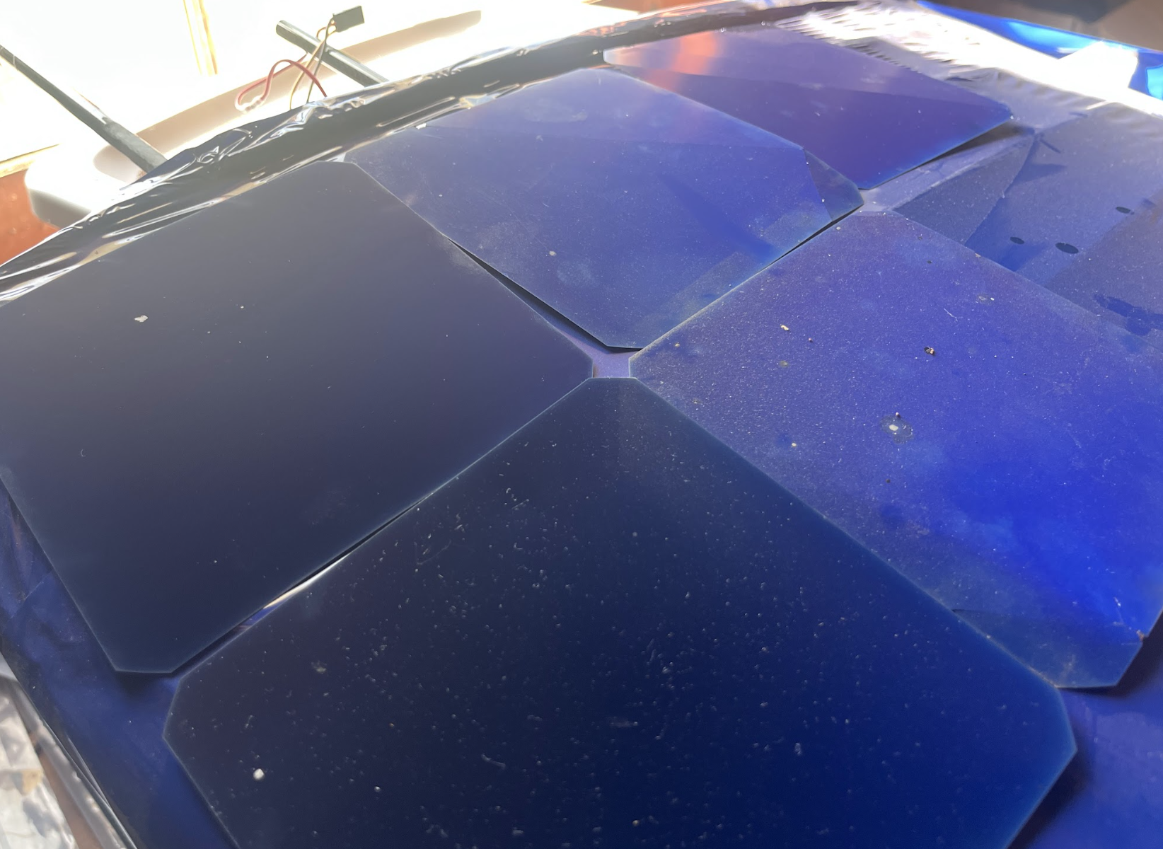
64 solar panels provide sufficient electricity for the aircraft to operate indefinitely (in clear skies) while the sun is more than ten degrees from the horizon.
-
![]()
Batteries
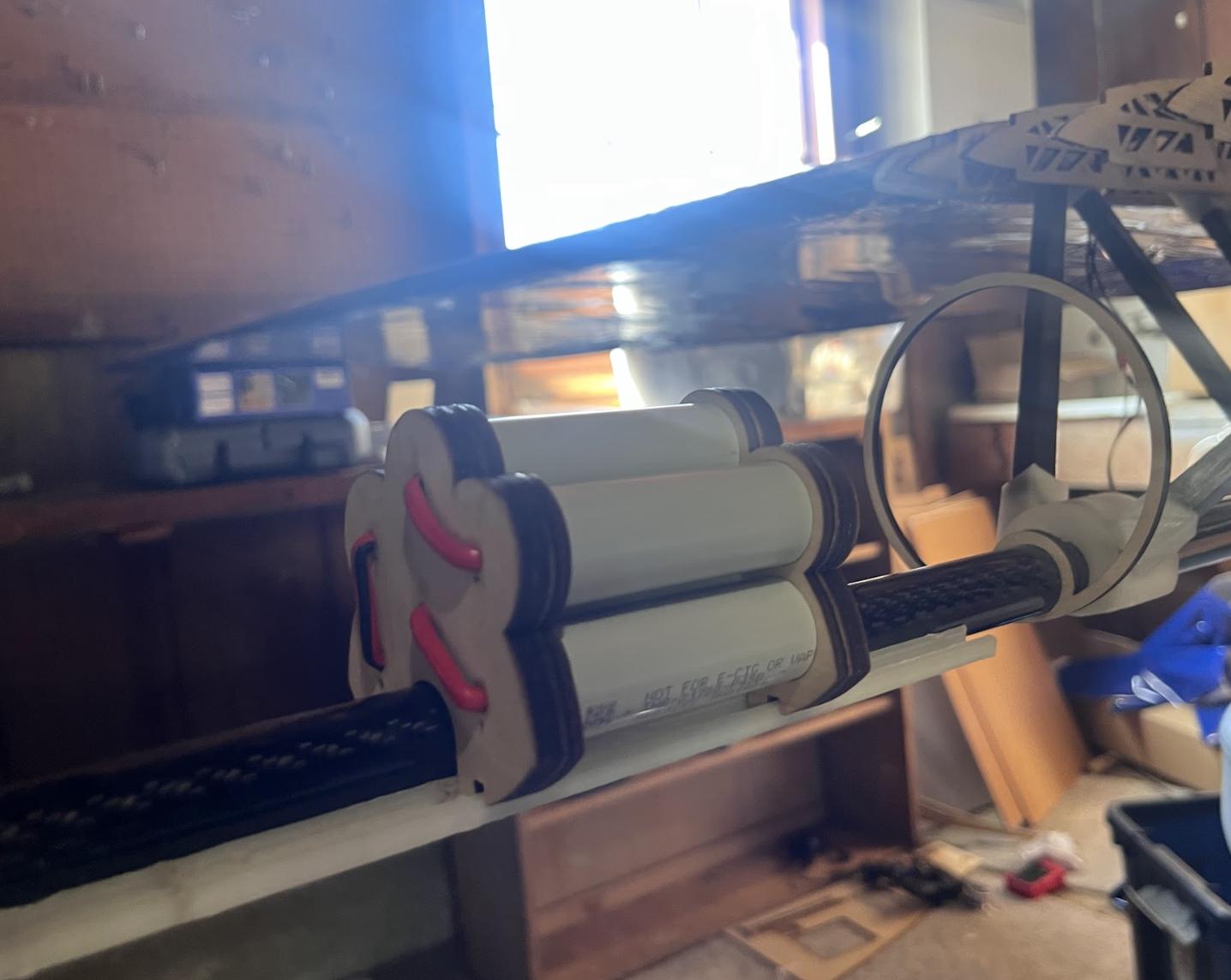
Six 24 volt LiPo batteries, power an additional two hours of emergency charge when weather conditions worsen.
WE DO THIS NOT BECAUSE IT IS EASY, BUT BECAUSE WE THOUGHT IT WOULD BE EASY.
Want to get involved? Learn more about this project!
While things never go according to plan in engineering, this project had more issues than I could have possibly imagined. There were failures due to low-quality products, incorrect design, and human error. I have learned that in order to be a great engineer, I have to separate my ego from the success of the project. Engineering is about pushing the limits of our ability to invent new ideas, so never failing is in fact the mark of a bad engineer. At least that’s my new perspective. Below is an abridged list of some of the challenges I’ve encountered:
Setbacks

One day’s worth of failed parts
-
Solar panels producing a fraction of the expected energy.
Making airfoils in CAD to be correct height but 17% too short, with the result they would not scale linearly.
-
Mac terminal failing to ping properly.
Project notes in Github being written in Turkish.
YOLO v8 not saving annotated images.
YOLO v8 not makoing identifications without a custom dataset.
All training data needing to be annotated by hand.
Operating service raising rates significantly above affordability for a teenager.
Terminal not recognizing Ardupilot.
Laser cutter breaking when running off-brand software.
Proprietary software not recognizing the laser cutter.
Camera system only connecting to Android phones.
Failing to complete project after two weeks of work!
-
Laser cutter being too small.
Insufficient space for equipment and fabrication.
Wood warping and fracturing.
Missing and damaged pieces of 3D printers.
Messing up wiring and all controls being mirrored.
Wood shifting while being cut.
Building before glue had arrived leading to seven broken pieces.
Incorrectly measuring and glueing each airfoil 48.8 mm apart instead of 46.8 mm apart.
3D printer not accepting PVA for dissolvable support structures.
Laser cutter failing to cut foam board.
Foam not adhering to standard cyanoacrylate glue.
Mylar coating forming diagonal ripples when placed under too much tension, increasing drag.
Drilling a hole through a carbon fiber pipe at an angle leading to fracturing.
Carbon fiber pipes not being built to the manufacturer’s specifications.
Trailing ends of many airfoils flexing and breaking under tension.
Ailerons being too weak to torsion forces.
Mylar not sticking to itself when the airfoil was too thin.
-
The Cube Orange+ flight computer not ‘talking’ to other devices.
The servo lines being too short to thread through the wing.
The battery using the wrong plug type.
Airspeed measuring pitot tubes not collecting data.
Battery management system burning out during testing.
-
Assuming solar irradiance was ~1000 watts/square meter but when only that high at peak.
Official servo specification being grossly exaggerated.
Solar panels taking weeks to arrive, slowing testing.
Estimating the coefficient too low, suggesting that the plane could fly on very little power.
Purchasing the wrong widths of carbon fiber pipes.
Supply chain issues causing delays in many specialized electronics.
Despite so many issues causing delays, breaks, and tears, I was able to overcome each and every one of them. I have had to learn how to adapt when issues arise and pivot focus when delays occur. If it were easy then it wouldn’t be interesting.
Tools
From the initial design to system testing, I taught myself to use a plethora of different tools, which allow a teenager without an advanced degree to design and construct a product which just a couple of years ago would have required a large team of professionals.
-
Autodesk Fusion 360
Wingshaper
Visual Studio Code editor
Notability
Ansys CFD
-
Ardupilot (autopilot)
Ultimaker Cura (3D printing)
Bambu Handy (3D printing)
LightBurn (laser Cutting)
Roboflow (machine learning)
Python (communications)
-
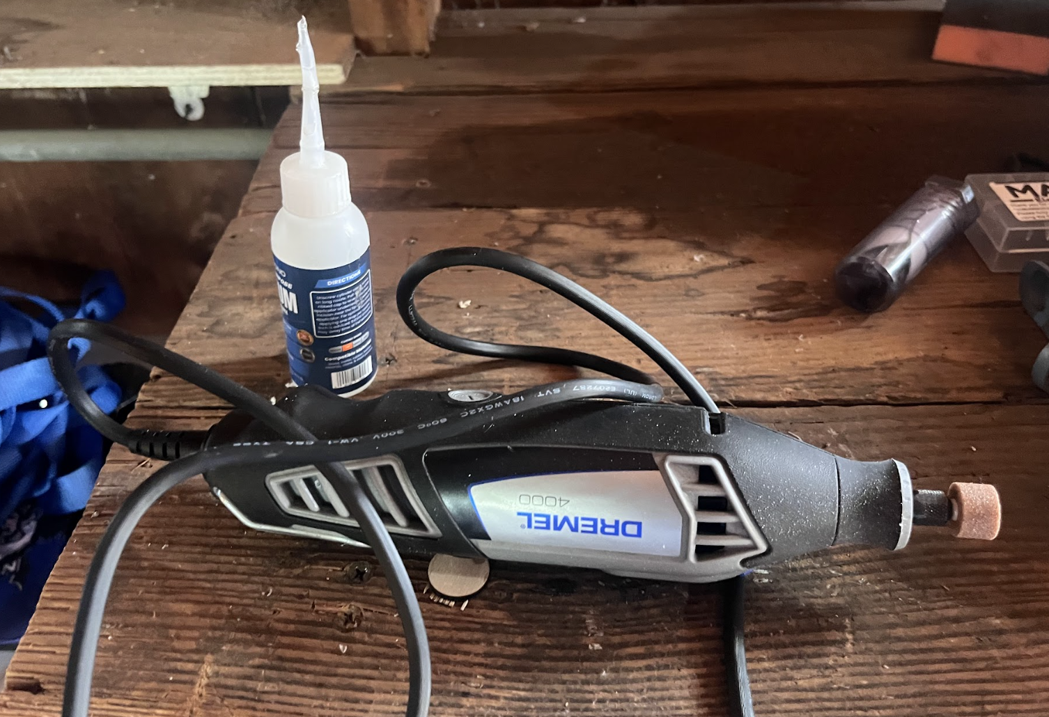
Laser cutter
dual extruder 3D printer
Multimeter
Raspberry Pi
Soldering Iron
Heat gun



Design
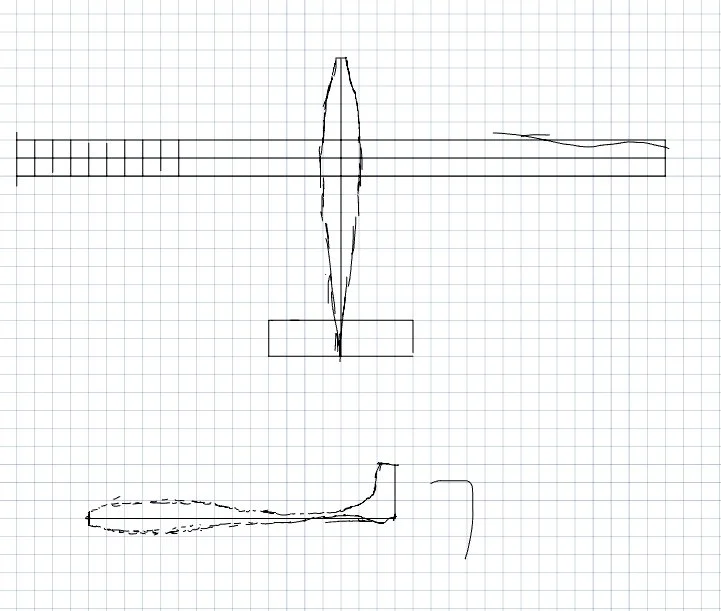
Initial Sketches
Design work started in August 2023. The initial idea was based on the mission objective, so the airframe itself looked very different from the final design, as it was based on a modified weather balloon. Everything to start was based on rough sketches and calculations. As more specifications were calculated, the blueprints became more and more precise.



Systems Definition and Interfaces
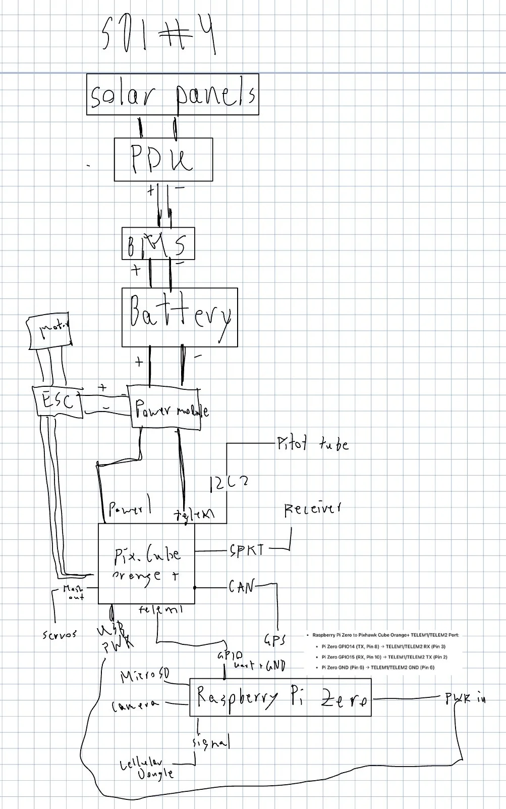
Systems definitions and interfaces allow an engineer to get a wide angle view of everything that will need to happen on a device, and how each system interacts with the others. While they started very simple, the systems definitions and interfaces used for this project grew rapidly in complexity.
Calculations
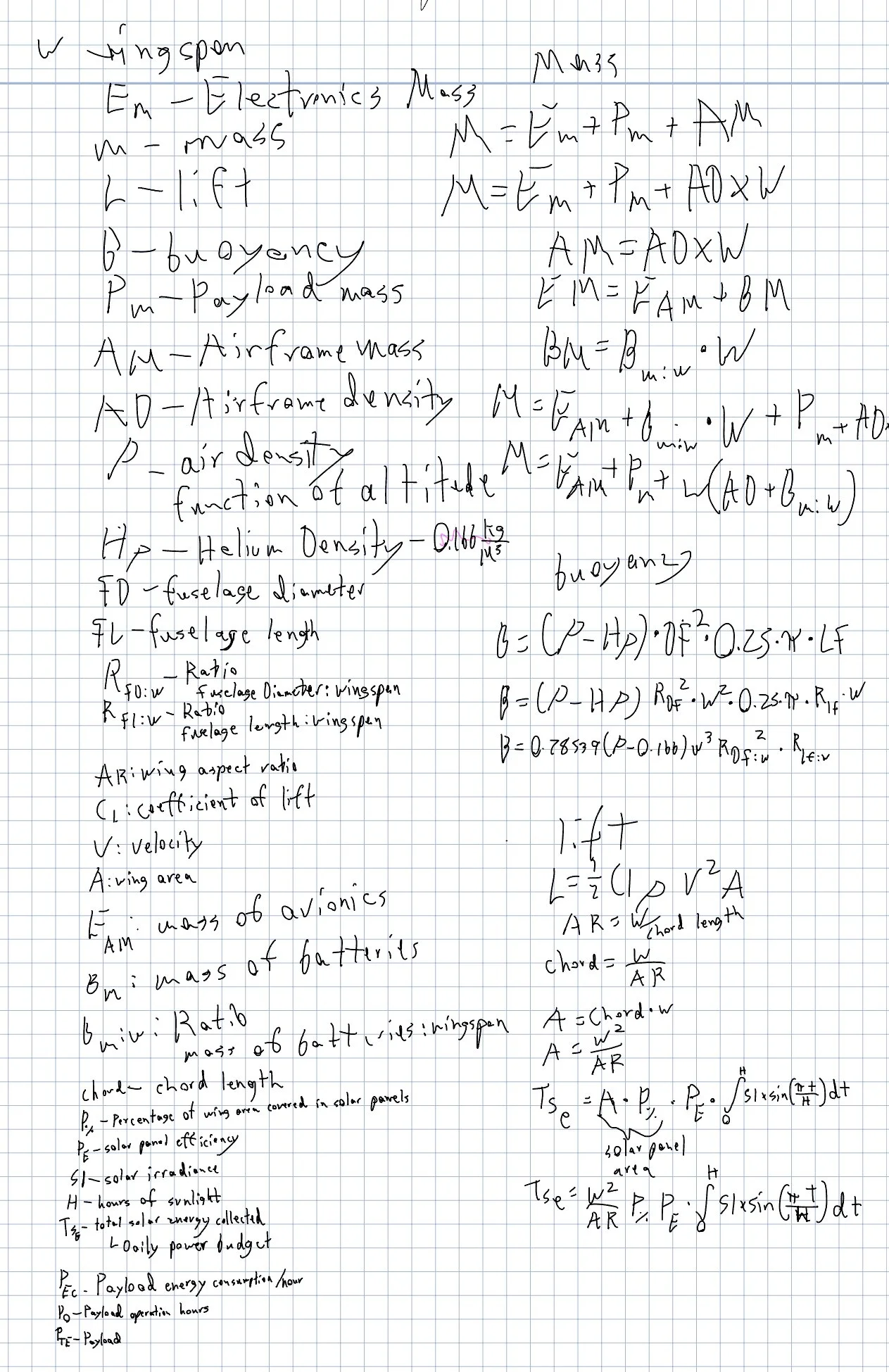
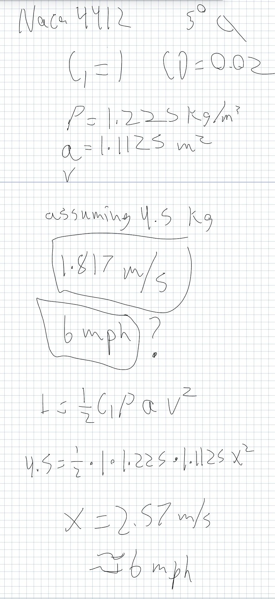
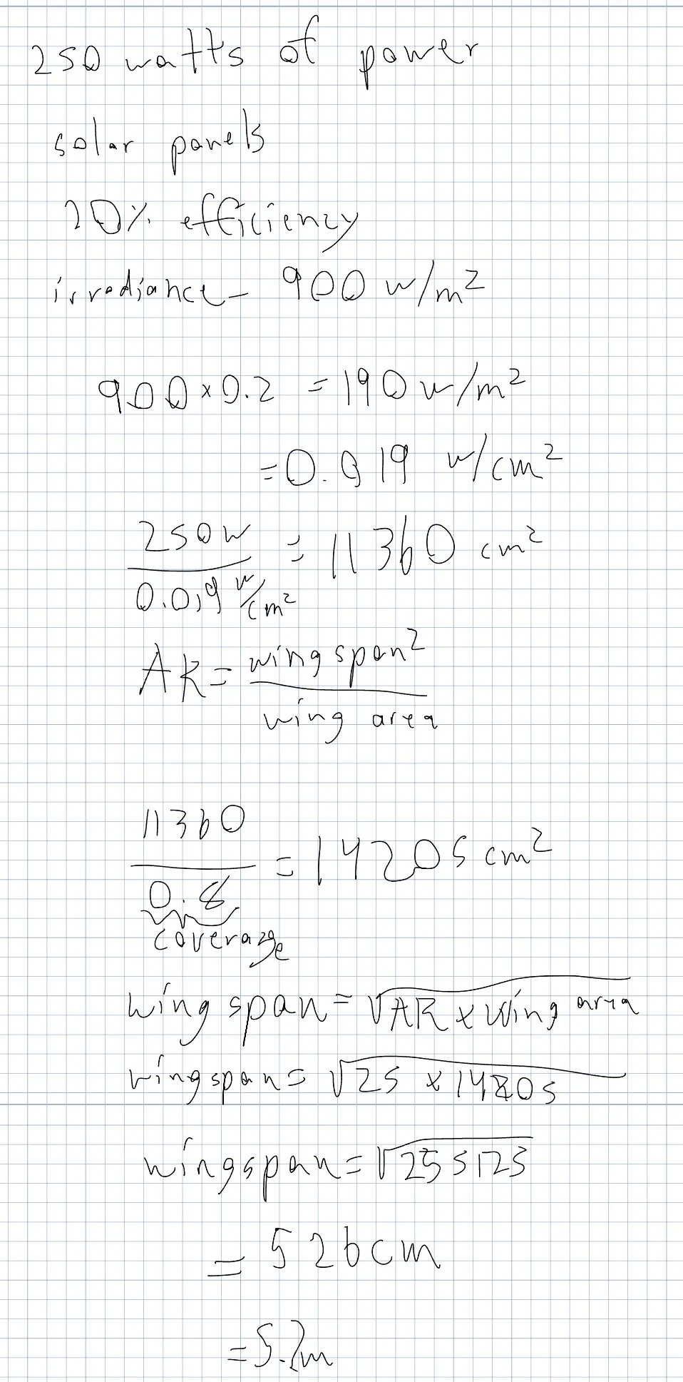
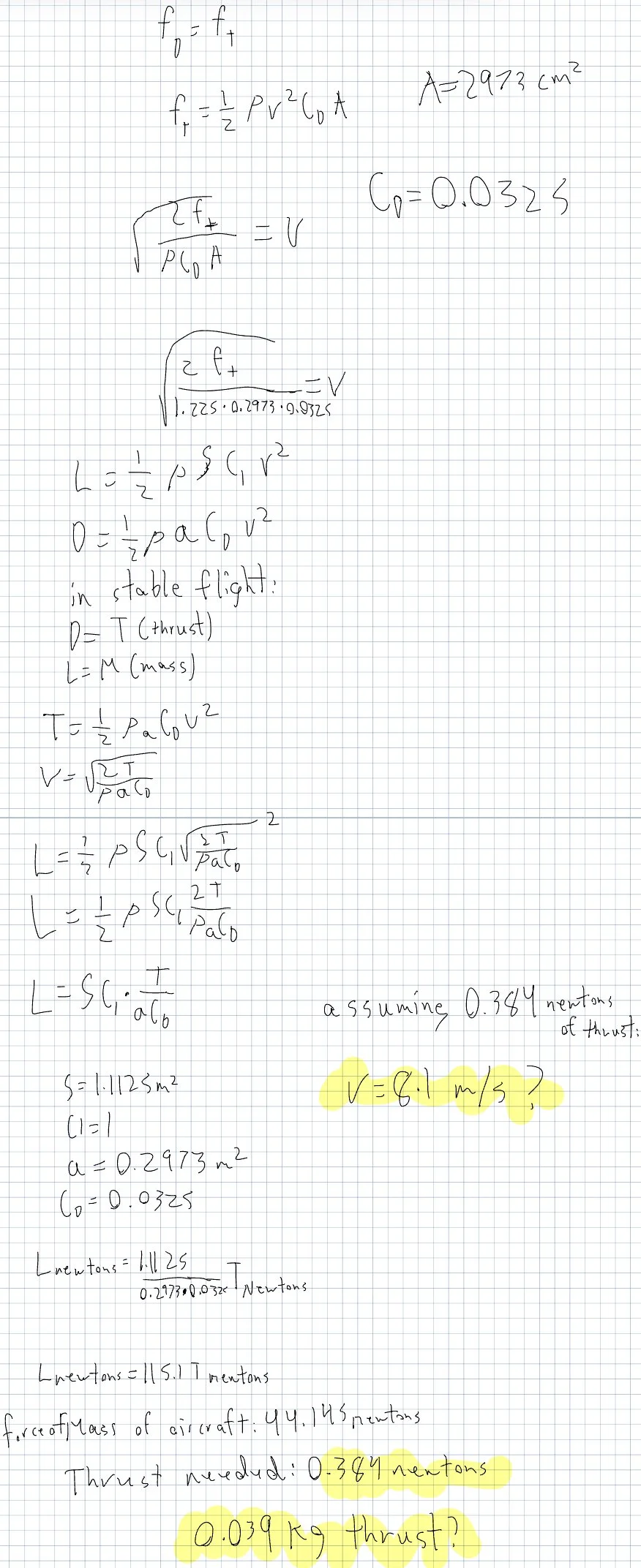
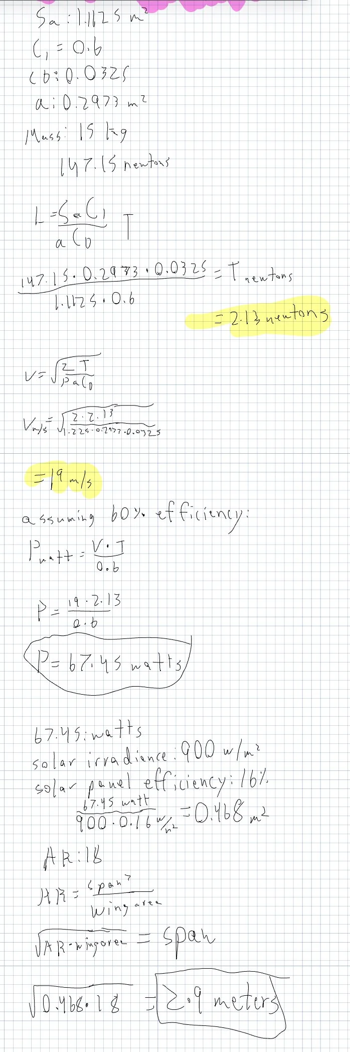
While making something fly is relatively easy, making a remote controlled aircraft fly for long periods of time only based on solar power can be quite difficult. Every design specification of the plane was selected through optimization equations. A total of over 75 variable were used, a sample of which is shown here.



CAD
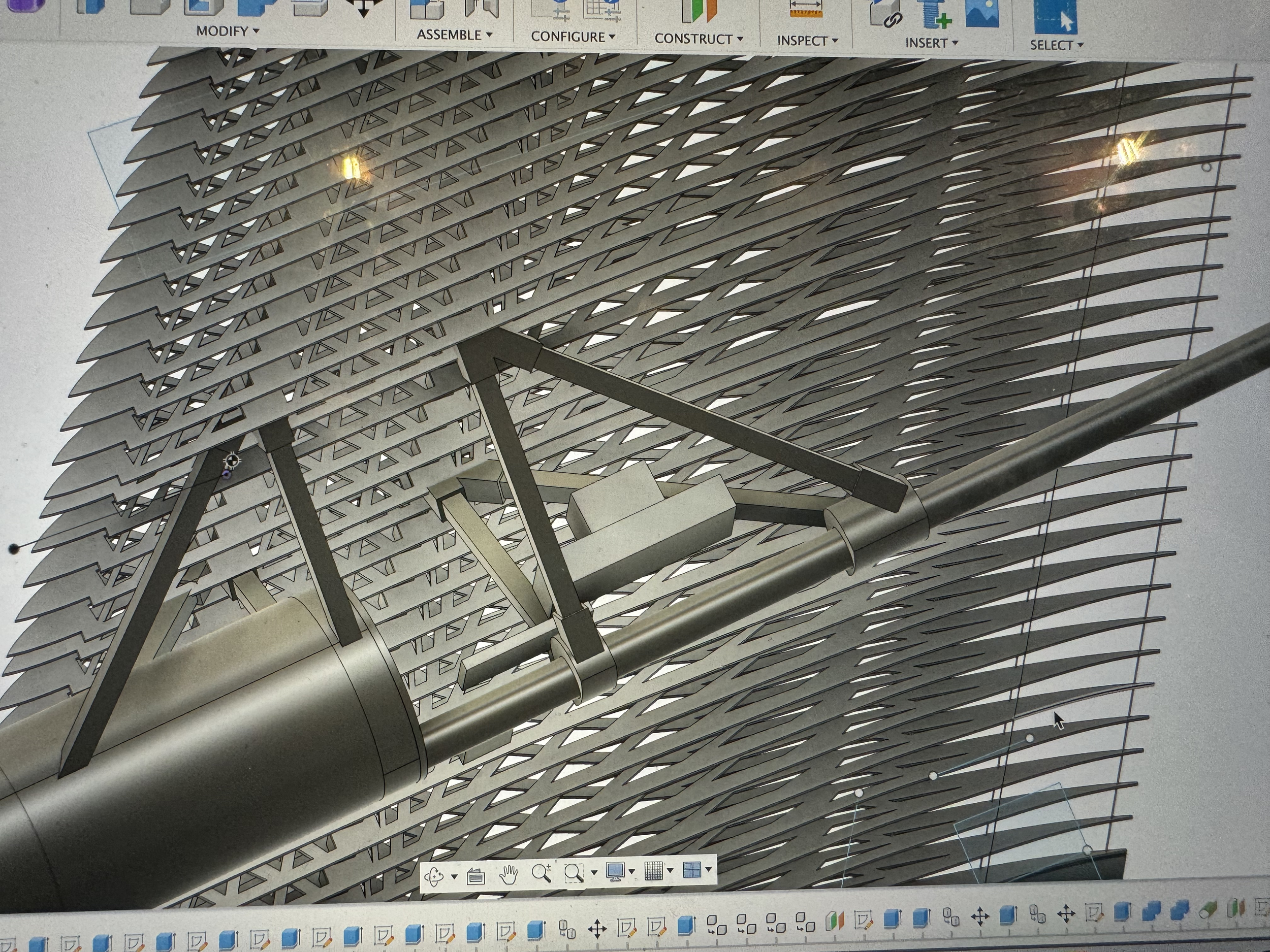
After several months of sketching, researching, calculating, and consulting with more experienced engineers, the designs were ready to be modeled with CAD. While most of the work was done with Autodesk Fusion 360, wing design was created on Wingshaper and simulations were performed with Ansys. The 3D models help with visualization, simulation, and fabrication down the road.
Fabrication
Materials Procurement and Testing
Based on the CAD model and design parameters, over 40 unique materials - from specialized mylar to 17 types of carbon fiber tubes - were procured. Each piece then was tested to confirm that it fulfilled (or at least came close to) its manufacturer’s specifications.

Every flat surface got very messy before being moved into one new space.
72 airfoils were laser cut from balsa wood. Each piece barely fit a single airfoil and each one took about seven minutes of cutting. Because of common malfunctions, and occasional fires, the laser cutter had to be managed at all times.

For each wing, the airfoils were slid onto two carbon fiber bars (built of four smaller bars each) and glued into place in parallel.
Servos for aileron control and wiring for solar panels were threaded through the wing.

For rear stability, each airfoil was connected by three ultra-thin carbon fiber spars with the addition of a 3D printed trailing edge for the more fragile areas.
A single airfoil. The exact cross section was unique for different parts of the wing, meaning it was crucial to keep all 72 organized. The holes cut out of the wood help lower the weight but are organized in a way which keeps the wing as rigid as possible.
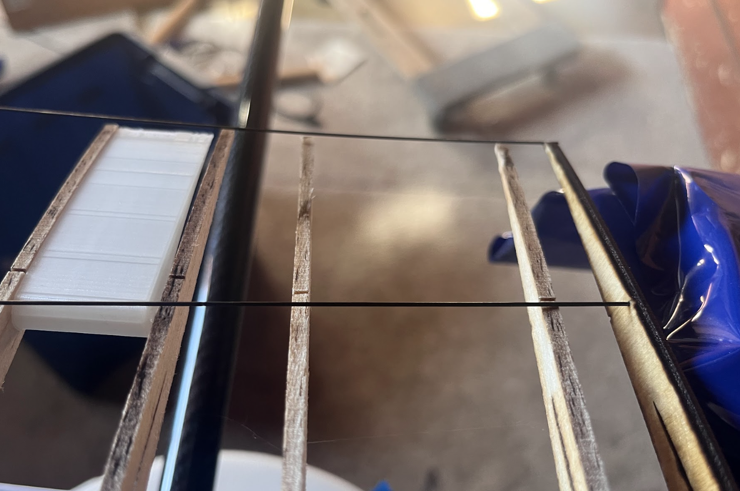
The wing surface is made of a mylar built for small aircraft. It was stretched onto the wing and would adhere itself to the frame and shrink with the application of heat.
Wing Manufacturing
By far the most challenging part of the fabrication process was building the wings, which are quite large (6 feet each!), use many specialized materials, and need to be built to very precise specifications in order to perform as expected.

The leading edge was built from foam board curved around the wooden frame.

The finished wings attached to the airframe!
Fuselage
The fuselage is made only of plywood, carbon fiber, and 3D printed LA-PLA, making fabrication simpler.
While some of the electronic doohickeys were purchased as is, due to the precise specifications of each part, many of them had to be assembled by hand. For example, the battery, which uses six 4500 mah cells wired in series and installed into the custom battery holder.

Because all electronics and hard-points are attached directly to the carbon fiber frame, the fuselage skin is only needed for aerodynamic properties, so it is 3D printed out of a single layer of extra light filament.

The base structure is built of a seven foot carbon fiber pipe, which acts as a primary hardpoint. Having a single piece for the superstructure makes the structure very strong and manufacturing simple as each piece slides on top.

The finished battery pack slides on 3D printed rails to allow for adjustments in the center of gravity.

The wings are attached to the body via a scaffolding made of carbon fiber and 3D printed connectors. This way, the wings are removable for transportation and allow lift to be generated in the center sections.

The motor and nosecone, built of wood and 3D printed surfaces, aligns the center of thrust and center of pressure, allowing the intake of optimal airflow to needed to maximize the cooling of the electronics without excessive drag.

Assembled!
Impact and Next Steps…
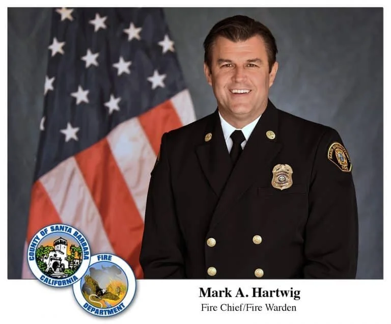
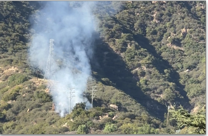
Fire Spotting: Santa Barbara County Fire Chief Mark A Hartwig has embraced the potential of the Stork and directed colleagues to begin testing during controlled burns this winter 2025/2026.
FAA Waiver: The County of Santa Barbara has agreed to sponsor the Stork under its F.A.A. research waiver (required of all experimental aircraft operating below 500 feet or within a fire containment zone.)
Communications: Chief Hartwig also has asked for relatively small modifications to allow the Stork to be used as a radio relay for backcountry communication (which require line of sight). Those modifications are currently in process.
Full Engineering Portfolio Download (PDF)